True Power vs. Apparent Power: Understanding the Difference
Introduction
AC power sources are essential pieces of equipment for providing flexible and reliable power generation. However, the concepts of power generation and power loss can be daunting for end users and sales personnel alike. This is especially true when it comes to talking about the different types of power quantities. What is the difference between true power and apparent power? Why is power referred to in both watts and volt-amps (VA)? This paper attempts to answer these questions and provide an understanding on the various aspects of power.
Energy and Power
In order to fully understand power, it is critical to grasp the concept of energy and how it relates to power. Energy is a force multiplied by a distance. An example is shown in Fig. 1. A force of 50 Newtons is applied to the block at point A in order to move it 10m to point B. The total energy expended is E = 50N * 10m = 500 Joules. The term "Joule" is the quantity used to define energy. If the same force were used to push the block only 5m, the energy expended would be E = 50N * 5m = 250 Joules. This makes sense since more energy would be required to push a block 10m rather than moving it 5m.


Fig. 1: Force Block Diagram
So what does energy have to do with power? Power is defined as the amount of energy expended per unit time. Looking back at the block example from Fig. 1, say it takes 5 seconds to move the block 10m from point A to point B. Then the total power, P = 500 Joules/5 sec= 100 Joules/sec = 100 Watts. So essentially, power is a force multiplied by a rate. Using this concept, it can be applied to electrical quantities.
This dynamic is the same when dealing with power in electronics. Voltage or "potential" is the force necessary to move electrons (rather than blocks). Current is actually a rate of flow of charges (in this case the charge of electrons) per second through a material with that voltage applied. By taking that force (voltage) multiplied by a rate (current), the end result is energy expended over time. This quantity is power. Thus electrical power is voltage multiplied by current.
P = V * I where power (P) is in watts, voltage (V) is in volts and current (I) is in amps
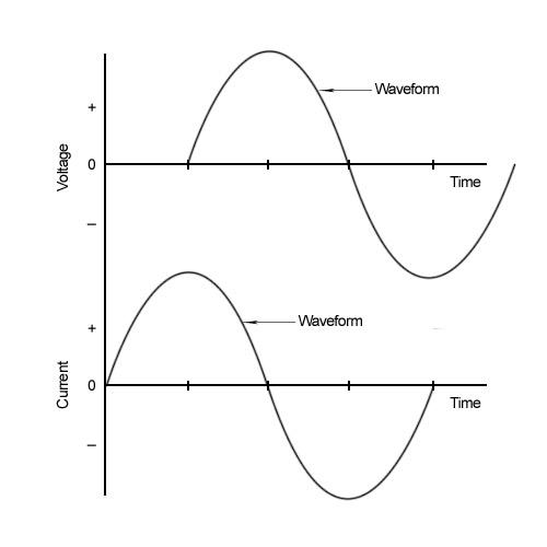
The voltage and current of an AC circuit are sinusoidal in nature (see Fig. 2). This means that the amplitude of the current and voltage of an AC circuit will constantly change over time. Since power is voltage times current (P= V*I), power is maximized when the voltage and current are "lined up" with one another. The peaks and zero points on the waveform for voltage and current occur at the same time (Fig. 3). When this happens, the two signals are said to be "in phase" with one another. Two waveforms are said to be "out of phase" or "phase shifted" when the two signals do not match up from point to point. So when are the voltage and current in phase? What causes them to shift so that they would be out of phase? This has to do with the circuit components involved in the system. Due to the behavior of voltage and current in AC circuits, power is a quantity that comes in several different flavors.


Fig. 2: AC Waveform


Fig. 3: In Phase Voltage and Current Signals
Circuit Components: To Shift or Not To Shift?
The three main circuit components are the resistor, the capacitor and the inductor. Each component has a different effect on the phase shift between voltage and current. A resistor causes no shift between current and voltage (a zero degree shift - shown in fig. 3). Power that is the result of a purely resistive load is known as "true" power. It is the power that performs work in the circuit and it is measured in Watts (W). This is the power that will drive a circuit board or a motor. It is the desired outcome of an electrical system.
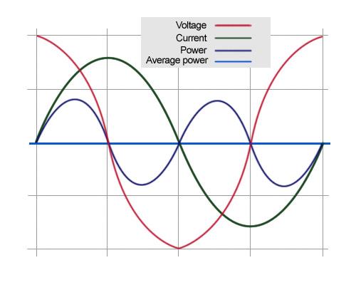
A capacitor and inductor will cause a 90 degree phase shift between voltage and current (fig. 4). The resulting power will have a value of zero every time the voltage or current has a zero value since the two quantities are multiplied to get power (fig. 5). This is not a desirable model because although the source is generating power, no work is being done at the load. This type of power is known as "reactive" power because it counteracts the effects of true power. Reactive power is the lazy brother of true power. True power is doing all the work while reactive power is actually taking away from the power in the system making the true power work harder to get the job done. It is measured in what is known as reactive volt-amps (VAr). A capacitive load will introduce negative reactive power and the voltage "lags" the current waveform by 90° (fig. 6). An inductive load will introduce positive reactive power and the voltage "leads" the current waveform by 90° (fig. 7). This is because capacitors "generate" reactive power and inductors "consume" reactive power.


Fig. 5: Voltage, Current and Resulting Power waveforms


Fig. 6: Negative Reactive Power - Voltage Lags Current


Fig. 7: Positive Reactive Power - Voltage Leads Current
Why are these values important? The reason is because all practical electrical applications will contain a combination of resistive, capacitive and inductive elements. Therefore, any practical AC circuit or system will have a combination of both true and reactive power which will vary the phase angle between voltage and current. The desired outcome is to maximize true power while limiting reactive power. Taking both into account, the end result of the tug of war battle between true and reactive power is called complex power. It is measured in volt-amps (VA).
The Power Triangle
The power triangle is shown in fig. 8. This gives a graphical representation of how all these quantities are related.


Fig. 8: The Power Triangle
- True Power (P): power that performs work measured in Watts (W)
- Reactive Power (Q): power that does not perform work (sometimes called "wattless power") measured in VA reactive (VAr)
- Complex Power (S): the vector sum of the true and reactive power measured in volt amps (VA)
- Apparent Power (ISI): the magnitude of the complex power measured in volt amps (VA).
- Φ = phase angle. This is the angle used to describe the phase shift between the voltage and current. The larger the phase angle, the greater the reactive power generated by the system.
In this case, the horizontal leg is the true power, the vertical leg is the reactive power and the hypotenuse is the complex power (fig. 8). True power is the work we want out of the system. As a result we are going to say that it is on the "true" axis (horizontal line). Since reactive power essentially "leeches" off of true power and does not contribute to powering the load, we'll define it separately and say it is on the "imaginary axis (vertical line whose value indicated by the letter "I" before the quantity). The apparent power is calculating by simply taking the magnitude of S (ISI -> magnitude of a value shown by the value with a vertical line on either side). For example, if the true power in a system is 4W and the reactive power is 3VAr, the complex power would be S = sqrt(4A2 + JA2) = 5VA This method of calculation is known as a vector summation.
Putting the Pieces Together
The important quantity to pull from this is the apparent power. The apparent power is the vector summation of both the true power and reactive power. That basically means that both the true and reactive power elements will affect the apparent power value. This will depend upon the magnitude of the true power, the magnitude of the reactive power and the phase shift between the voltage and the current. Apparent power is used to define the total power delivered to a load. This is also how ratings are often described on power sources, including the EEC series. For example, the power source is a l000VA unit. That VA quantity refers to the apparent power.


Fig. 9: Black Box Example
Take a look at the image in Fig. 9. This is a black box example. There are three parts to this diagram: the input, the system and the output. The user has to input a certain amount of power, the system performs the work and the end result is that there is output power. In a perfect world with no losses, the input power would be equal to the output power. However, there will always be losses on a system. Say that the required output to run a motor is 1000VA. It is known that 200VA of power are "lost" in the system due to the reactive power components. This means that the user will need to input at least 1200VA of power to run the motor. Since 200VA is lost in the "work" portion of the system, the output power = 1200VA - 200VA = 1000VA. Otherwise, the motor will not have enough power to operate. It is important to know the phase shift between the voltage and current because this gives a value for reactive power. This value needs to be known so that enough power can be applied at the input to get the desired output.
The above example outlines the importance of calculating losses in a system. Without knowing how much power is lost on a system, it is possible that the source would not have the necessary power to supply the load. The end result would either be that the source would be unable to supply the load or the system would operate at a highly inefficient rate. Therefore it is necessary to calculate the power consumption of the entire system rather than just the load so that the source can supply the necessary amount of power.
Conclusion
The apparent power is a combination of both reactive power and true power. True power is a result of resistive components and reactive power is a result of capacitive and inductive components. Almost all circuitry on the market will contain a combination of these components. Since reactive power takes away from true power, it must be considered in a system to ensure that the apparent power output from a system is sufficient to supply the load. This is a critical aspect of understanding AC power sources because the source must be capable of supplying the necessary volt-amp power for a given application. As with any product, understanding the needs and specifications of the end user will ensure a successful application.


