Operator Safety Circuits:
SmartGFI® vs. Conventional GFI
The Standard Household GFI Safety Circuit
Typical electrical circuits in a home contain three wires. One wire is called the "hot" wire. The second wire is called the "neutral" wire. The third is an earth ground wire. The earth ground wire is not meant to carry any current under normal operation.
Under normal conditions the current required to operate a product travels through a circuit starting at the power source and through the “hot” wire into the product. It then travels out of the product and back to the power source via the "neutral" wire. Remember that all of the current flowing into a product through the “hot” wire should return back to the source through the “neutral” wire. However, if the product becomes short-circuited to ground then current will flow directly to ground and bypass the neutral return path. This could happen if a person inadvertently completed the circuit to ground.
A household GFI circuit compares current that is on the “hot” and “neutral” lead. If they are not the same and the fixed limit of the GFI is exceeded then power to the device is shut down by a high-speed trip circuit in usually less than 10 milliseconds. GFI circuits are typically found in kitchens, bathrooms and basements, which are considered by the National Electrical Code to be areas of higher hazard due to the possibility of water contact in the presence of current should a ground fault occur.
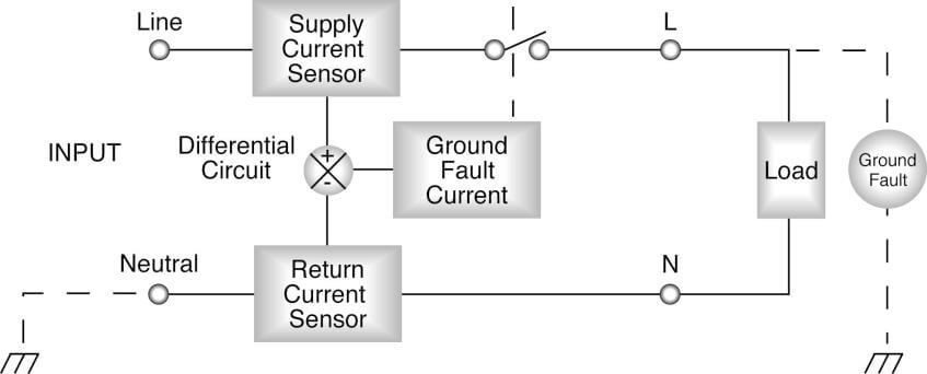
The GFI performs this function by using two sensing coils, which measure the current going out of the hot wire and coming back through the neutral wire (See figure 1). Typical household GFI circuits have a current trip level of around 7mA, which is much lower than the total current usually flowing in the circuit that they are protecting. The circuit that is protected can carry enough current to be fatal. Most household circuits can carry 10 amps of current or more. The reason that the GFI is set to a lower trip point is safety. In a normal condition current should not be flowing in the ground circuit so the threshold for shutdown can be set at a very low level to minimize current that would flow through the individual in the event of a fault.


Figure 1: Standard Household GFI Safety Circuit
Application of GFI Safety Circuits in Electrical Safety Testing
The circuit theory of GFI has now been applied to Electrical Safety Testing to provide operators with a similar type of protection from electrical shock. In typical high voltage testing applications users are exposed to the risk of electrical shock. Some Hipot testers are capable of providing output current in excess of 5mA. This is a current level that under some conditions could create an inability of the operator to let go if they came in direct contact with the high voltage. One key area of concern has been the condition where a DUT (Device Under Test) has a fault where the hot wire touches the case providing a path for the electrical safety testers high voltage output to the DUT’s case. This is not a key concern when the DUT case is grounded since the current will follow the path to ground and bypass an operator that might come into contact with the DUT. However, the same situation when the DUT case is floating can present a risk. If the return lead becomes disconnected then there is no path for the current to return to the source. With the DUT floating, the case does not have a path to ground so an operator coming in contact with the DUT could complete the circuit. We can use a similar theory to that of household GFI circuits for electrical safety testing applications. This reduces the risk of the operator receiving an electrical shock in this ungrounded DUT condition. The GFI circuit can also protect operators who come into direct contact with the high voltage output of the electrical safety tester.
“Conventional” Safety Testing GFI Circuit
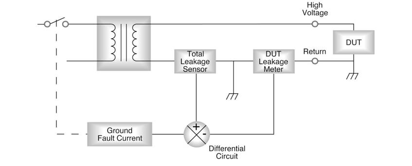
In order for the GFI circuit to properly work in electrical safety testing applications, the safety tester’s return lead needs to be ungrounded (floating). Having the return lead floating means that the case of the DUT, to which the return lead is normally connected, must also be isolated from earth ground. A conventional GFI works similar to the household GFI in that a comparison measurement is made. Where one point of measurement senses the current returning from the DUT through the return and the other point of measure is return current combined with current coming back through earth ground. With a good DUT that is floating these measurements should be almost identical since very little current should return through the ground connection. If there is a condition whereby the operator comes into contact with the high voltage circuit and completes a path to ground the GFI will sense an excessive differential between these two points and shut down. However, as you can see from figure 2 if the DUT is grounded all the current returns directly through the ground point bypassing the other leg of the GFI. This results in a difference in measurement between these two points causing a false GFI failure indication. If you have to test a grounded DUT that will require the return to be grounded, then the GFI circuit on a conventional GFI circuit must be manually disabled. A true safety feature must be active at all times and not require the intervention of the operator to make a decision.


Figure 2: Conventional Safety Testing GFI Circuit
Problems with the “Conventional” Safety Testing GFI Circuit
A key problem with conventional GFI circuits is that in some test conditions they have to be shut off. This means the operator needs to intervene with the instrument’s settings. There are several risks involved in this. One risk is operator error due to the necessity of accessing the system setup menus, which may inadvertently lead to the changing of other settings within the instrument’s menu. Another risk is the operator forgetting to turn the GFI back on when returning to perform a test in a floating return condition. This could be a significant safety risk since the operator may be unaware that a key safety feature of the instrument is in the disabled mode.
How the Patented SmartGFI® System Works
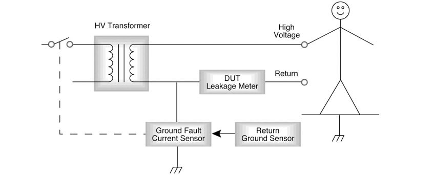
Associated Research’s SmartGFI automatically recognizes the DUT’s configuration and automatically enables or disables the GFI circuit accordingly (see figure 3). In the case that the DUT is earth grounded, the “return ground sense” circuit automatically disables the GFI circuit and the instrument operates in a grounded return mode of operation. This mode allows the user to perform their tests normally without the operator having to manually change the instrument’s configuration. It is important to note that even though the SmartGFI is disabled in grounded return mode it is most likely because the DUT case is grounded. This in itself provides a level of safety for the operator since during a fault condition the current will bypass the operator and return directly to the source even if they were in contact with the DUT.
However, unlike conventional GFI systems once the test conditions change from grounded return back to floating return the SmartGFI circuit will automatically be enabled. Unlike conventional GFI circuits the SmartGFI system does not use a comparison measurement for detection of ground fault current. Since the circuit can automatically enable and disable itself it can be setup to monitor actual fault current through ground. This greatly simplifies the circuit and improves the overall reliability of the SmartGFI. The SmartGFI circuit will shut down high voltage if leakage in excess of 450µA is detected through the ground circuit. This is a high-speed shutdown circuit that disables the high voltage in less than 1 millisecond.
Many testing applications are very versatile and production lines can quickly be re-configured to manufacture and test a wide range of different products. In some cases these products might be grounded via a production roller platform requiring the return of the electrical safety tester to be grounded and on others the return may be floating. SmartGFI ultimately provides the most effective safety protection since it is an active circuit monitoring the configuration of the return connection and automatically sets itself accordingly. By eliminating the operator from the equation the SmartGFI works as an effective safety circuit because it does not require human interaction that could invite operator error.


Figure 3: Patented SmartGFI System


