EEC 85xx Power Supply Connection
Introduction
This application note provides essential guidelines for proper connection of the 8500 series power supply to ensure safe and reliable operation. Adhering to these recommendations will help prevent damage to both power supply and connected devices.
1. Input Voltage and Current
A dedicated mains power source of 100 – 240V AC ± 10%, (50/60Hz ) single phase is required for models 8505, 8512, and 8520. Models 8530 & 8540 require a 200 – 240V AC ±10%, (50/60Hz) balanced/single phase input source. Please read the sticker on the rear panel of the instrument to be sure the proper input voltage is provided before powering your instrument ON. Model 8560 requires a 200 - 240V ± 10% single phase / 3 phase input source or a 346 - 416V ± 10% 3 phase input sources.
| Models | 8505 | 8512 | 8520 | 8530 | 8540 | 8560 |
| Input Voltage | 100-240V±10% | 200-240V±10% | 1Ø/3Ø3W: 200-240V±10%; 3Ø4W: 346-416V±10%; |
|||
| Input Current Max | 8A | 18A | 30A | 22A | 30A | 1Ø: 45A; 3Ø3W: 38A; 3Ø4W: 22A |
The following chart lists the wire configuration that must be used for connection to the input and output of the different models:
| Models | INPUT | OUTPUT |
| 8505 | 14AWG/2.08mm² | 22AWG/0.326mm² |
| 8512 | 12AWG/3.31mm² | 16AWG/1.31mm² |
| 8520 | 12AWG/3.31mm² | 14AWG/2.08mm² |
| 8530 | 12AWG/3.31mm² | 12AWG/3.31mm² |
| 8540 | 12AWG/3.31mm² | 10AWG/5.26mm² |
| 8560 | 1Ø2W: 8AWG/8.37mm² 3Ø3W:10AWG/5.26mm² 3Ø4W: 12AWG/3.31mm² |
6AWG/13.3mm² |


The rear panel terminal covers should be used to prevent electric shock. The input/output terminals must be covered when using this product.
2. Connections and Wiring:
Choose appropriate mains power and follow the connection diagram listed below for the type of power that is available. Use the correct connectors rated for the application and secure each connection to prevent power issues.


Before connecting power to this instrument, the protective ground (earth) terminals of this instrument must be connected to the protective conductor of the line (mains) power cord. The main plug shall only be inserted in a socket outlet (receptacle) provided with a protective ground (earth) contact. This protective ground (earth) must not be defeated by the use of an extension cord without a protective conductor (grounding).
8505, 8512, and 8520 - Input Requirements
Voltage 1Ø2W: 100 - 240 V ± 10%


Figure 1: 1P2W 120 Volts L1 – N – Ground


Figure 2: 1P2W 230 Volts L1 – N - Ground


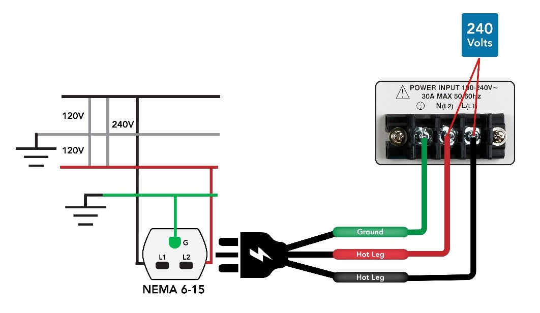
Figure 3: 1P3W 240 Volts L1 – L2 – Ground
8530 - Input Requirements
Voltage 1Ø2W: 200 - 240 V ± 10%


Figure 4: 1P2W 230 Volts L1 – N – Ground


Figure 5: 1P3W 240 Volts L1 – L2 – Ground
8540 - Input Requirements
Voltage 1Ø2W: 200 - 240 V ± 10%


Figure 6: 1P3W 240 Volts L1 – L2 – Ground


Figure 7: 3P3Wire 208 Volts L1 - L2 – Ground
8560 - Input Requirements
Voltage 1Ø: 200 - 240 V ± 10%


Figure 8: 1P3W 240 Volts L1 – L2 - Ground


Figure 9: 1P3W 208 Volts L1 - L2 - Ground
Voltage 3Ø3W: 200 - 240V ± 10%
Phase to Phase Voltage: 208V


Figure 10: 3P3W 208 Volts L1 - L2 – L3 - Ground
Voltage 3Ø4W: 346 - 416V ± 10%
Phase to Phase Voltage: 380V
Phase to Neutral Voltage : 280V


Figure 11: 3P4W 380 Volts L1 - L2 – L3 – Neutral – Ground
3. Disclaimer
The end user is responsible for ensuring compliance with all safety standards and regulations during the installation and operations of the power supply. Any electrical installation should be carried out by qualified and licensed professionals in accordance with local electrical code. Always refer to the manufacturer’s documentation for specific details.


